
Introduction — why this matters
Have you ever wondered why a machine that should run for years needs attention after only a few months? Recent field checks show unexpected downtime rising by roughly 12% across mid-sized factories, and that begs a simple question: what are we missing? An electric motor is often the quiet backbone of a line, but small inefficiencies add up fast (and yes, I’ve seen the spreadsheets). In this short piece I’ll walk through real faults, user pains, and sensible fixes that work on the shop floor. Let’s move from theory to the tools that actually make a difference.
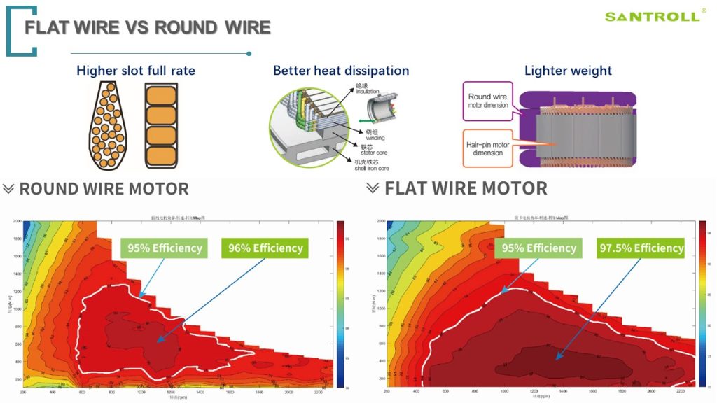
Deeper problems beneath the surface
When I examine the limits of a brushless electric motor, a few patterns repeat: sensors placed poorly, controllers undersized, and cooling paths ignored. These are not exotic failures; they are practical mistakes—simple, avoidable. As I noted above, downtime climbs when small issues compound. Look, it’s simpler than you think: a mismatched inverter can stress the rotor and stator, create torque ripple, and shorten bearing life. I’ve watched teams chase the wrong symptoms (vibration, heat) while the real fault lived in the controller firmware or in faulty Hall sensors.
Why do standard fixes fail?
Most standard fixes treat symptoms. Engineers add lubrication, tighten mounts, or replace a bearing. Those actions help—temporarily. They fail when root causes are electrical or thermal: inadequate power converters, poor winding designs, or insufficient thermal paths in the housing. I’ve been in shops where an upgraded controller would have prevented three bearing failures in a year, but the team only replaced bearings because that’s what the maintenance schedule told them. — funny how that works, right?
Principles for next-generation improvement
Now we shift forward. If you want durable performance, you need principles that guide choices: precise control, thermal management, and matched components. New control algorithms that reduce torque ripple and smart cooling channels reduce stress on components. For example, smart field-oriented control reduces current peaks and lowers heat in the winding. When paired with proper sensor placement and an adequate inverter, you get longer life and fewer service calls.
What’s next for selection and design?
I also watch rising interest in the permanent magnet synchronous motor for applications that need compact power and steady torque. These motors can be efficient and reliable when designers respect magnet demagnetization limits and include robust thermal monitoring. In practice, that means choosing a controller with good current sensing, planning for cooling, and testing for real load cycles on the floor. We test prototypes under both steady and pulsed loads; the difference in failure modes is revealing — short, sharp loads often hurt more than steady ones.
Three practical evaluation metrics before you buy
To close, I recommend three simple metrics to judge any solution: thermal margin, control bandwidth, and system-level compatibility. Thermal margin tells you how much extra heat the motor can tolerate before performance drops. Control bandwidth indicates how well the controller will handle rapid changes without inducing torque ripple. System-level compatibility means the motor, inverter, sensors, and mechanical mounting are chosen together—not piecemeal. Use these metrics as a quick checklist. I use them on every project, and they cut guesswork by half.
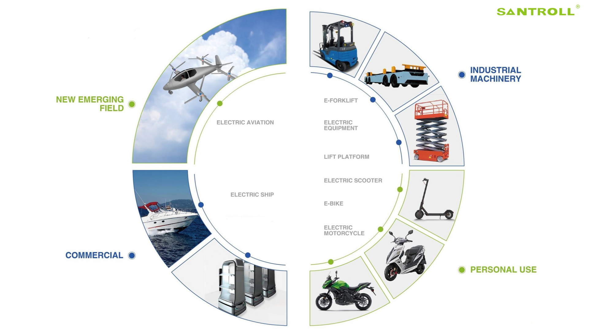
We’ve tried many tweaks over the years; some worked and some didn’t. My view is pragmatic: measure, match, and monitor. If you start with that, you’ll avoid the common traps I see on sites every month. For reliable components and sensible pairings, I often point teams toward suppliers who document both performance and test conditions — that transparency matters. For reference and supplier details, see Santroll.